Stick
Veronte Autopilot 4x is compatible with joysticks that use PPM, CAN bus, USB, Serial, etc.
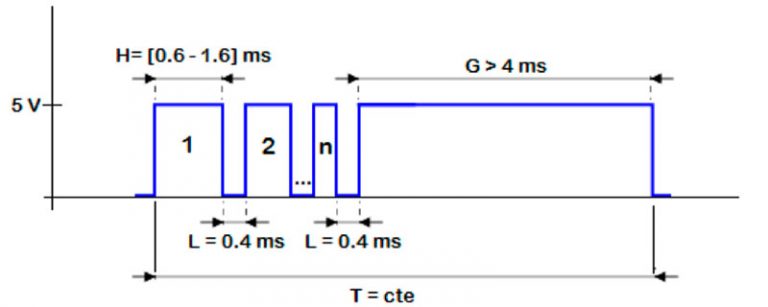
If the PPM level is 3.3V, the following Autopilot 4x pins can be used:
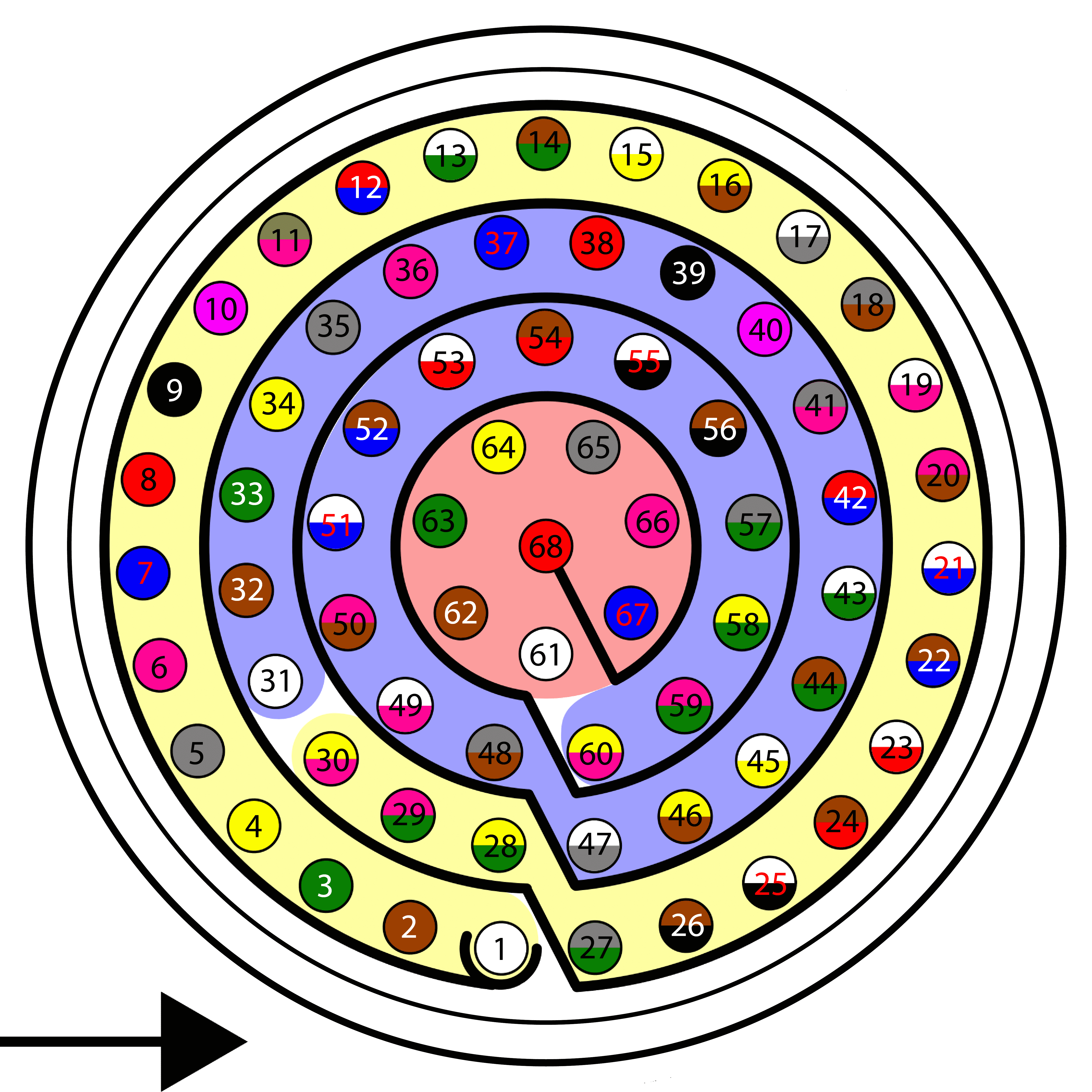
| PIN | Signal | INTERNAL POWER DOMAIN | Color code |
|---|---|---|---|
| 1 | I/O_0_MUXED | A | White |
| 2 | I/O_1_MUXED | B | Brown |
| 3 | I/O_2_MUXED | A | Green |
| 4 | I/O_3_MUXED | B | Yellow |
| 5 | I/O_4_MUXED | A | Gray |
| 6 | I/O_5_MUXED | B | Pink |
| 7 | I/O_6_MUXED | A | Blue |
| 8 | I/O_7_MUXED | B | Red |
| 9 | GND* | Black | |
| 10 | I/O_8_MUXED | A | Violet |
| 11 | I/O_9_MUXED | B | Gray - Pink |
| 12 | I/O_10_MUXED | A | Red - Blue |
| 13 | I/O_11_MUXED | B | White - Green |
| 14 | I/O_12_MUXED | A | Brown - Green |
| 15 | I/O_13_MUXED | B | White - Yellow |
| 16 | I/O_14_MUXED | A | Yellow - Brown |
| 17 | I/O_15_MUXED | B | White - Gray |
| 18 | GND* | Gray - Brown | |
| 55 | EQEP_A | A for autopilots 1 and 2 B for autopilot 3 |
White - Black |
| 56 | EQEP_B | Brown - Black | |
| 57 | EQEP_S | Gray - Green | |
| 58 | EQEP_I | Yellow - Green | |
| 59 | GND* | Pink - Green |
Caution
PPM signal must be into the Veronte Autopilot 4x voltage ranges. Some joysticks may need an adaptation board, please ask our team to check compatibility.
Connector for harness is provided with 3.5 mm stereo plug connector as follows:
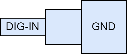
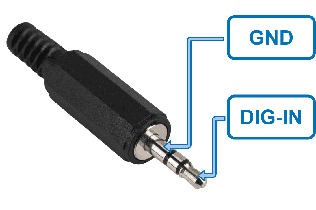
- To use the joystick with PPM in the system, connect the PPMout of the trainer port to a digital input of Veronte Autopilot 4x and configure that digital input according to the PPM Stick - Integration examples section of the 1x PDI Builder user manual.
- When using a USB joystick, the software installation with Autopilot 4x is detailed in the USB joystick - Integration examples section of the 1x PDI Builder user manual.
- For joysticks with signals different from PPM or USB, read the Virtual Stick - Integration examples section of the 1x PDI Builder user manual.
© 2025 Embention. All rights reserved.